Introduction of Surveying

Geoinformatics

Geoinformatics can be broken down into two main components: the measurement of geoinformation and the management of geoinformation.

The measurement of geoinformation involves determining “what is where” (known as geometry) and “what is what” (known as identification). This typically involves using various tools and techniques to collect data about the Earth’s surface and features, such as satellite imagery, aerial photography, and ground-based surveys. The data collected is then analyzed and interpreted to determine the location and characteristics of different geographical features.

In more detail, the process of measuring geoinformation generally includes the following steps:

  1. Geometry: Determining the location and shape of geographic features. This is often done using coordinates, which specify the position of a point on the Earth’s surface in terms of its latitude, longitude, and elevation. Other methods for determining geometry include the use of maps, satellite imagery, and aerial photography.
  2. Identification: Identifying the types of geographic features present at a given location. This may involve analyzing the physical characteristics of the feature, such as its size, shape, and texture, or it may involve examining other data sources, such as land use records or environmental databases.

Once geoinformation has been measured, it must be managed effectively in order to make it useful for decision making and analysis. This involves several key tasks:

  1. Management: Storing, retrieving, and presenting geoinformation in a way that makes it accessible and usable by a variety of stakeholders. This may involve creating maps, reports, or other visualizations of the data, as well as developing databases and other systems for storing and organizing the information.
  2. Manipulation: Analyzing geoinformation to extract insights and support decision making. This may involve performing spatial analyses, such as overlaying multiple datasets to identify patterns or trends, or conducting statistical analyses to better understand the relationships between different variables.

Overall, the field of geoinformatics encompasses both the measurement and management of geoinformation, with the goal of providing accurate, up-to-date, and actionable information about the Earth’s surface and features.

Exploring Land Measurement Tools and Techniques

When it comes to measuring land, various tools and techniques have been employed throughout history, ranging from primitive methods to modern technology. Here’s a breakdown of some commonly used tools and techniques:

  1. Primitive Techniques:

    In ancient times, people relied on simple methods like pacing, using hands for estimation, and using rods for rough measurements. These methods were often based on intuition and human judgment. For instance, in the Vedic age, pacing was a common method where people walked a certain distance to measure land. The human figure was often used as a reference for estimation.

  2. Pacing:

    Pacing involves measuring distances by counting the number of steps taken. While this method is relatively simple and doesn’t require any equipment, its accuracy can vary depending on the individual’s stride length and consistency. Typically, the degree of accuracy is around 1 in 100, meaning there might be a slight margin of error. A common rule of thumb is that about 40 paces equal 100 feet.

  3. Land Measurement Techniques:

    As humans settled and began farming, more accurate methods of measuring land became necessary. Chains and compasses were among the earliest tools used for this purpose, followed by tapes and theodolites (an instrument for measuring horizontal and vertical angles). Electronic land surveying techniques, such as Total Stations and Global Positioning System (GPS) technology, offer greater precision and speed than traditional methods.

  4. Aerial Photogrammetry:

    This technique involves capturing aerial photographs of the land and using them to create detailed maps and measurements. It provides a bird’s eye view of the terrain, allowing for comprehensive analysis.

  5. Satellite Remote Sensing:

    Satellites orbiting the Earth capture imagery and data that can be used for land measurement purposes. This method offers a global perspective and is particularly useful for large-scale surveys.

  6. GPS (Global Positioning System):

    GPS technology enables surveyors to pinpoint locations on the Earth’s surface with exceptional accuracy using signals from satellites. It has revolutionized land surveying by providing real-time positioning data.

Surveying and Laying out

Surveying is the practice of determining the relative positions of points on, above, or below the Earth’s surface by taking linear and angular measurements. It encompasses the art of establishing the spatial relationships between various locations, whether on a horizontal plane or in vertical dimensions.

Levelling, a subset of surveying, focuses specifically on determining the relative heights of different points on the Earth’s surface. This involves measuring elevations and gradients along vertical planes.

Surveying is a vital discipline in geomatics, which involves the measurement, analysis, and management of geographic information. At its core, surveying involves two main categories: surveying and laying out.

The first category, surveying, refers to the process of collecting data about the physical features of the land, such as its shape, slope, elevation, and location of structures. This is done using various surveying instruments and techniques, such as total stations, GPS, and levelling. The data collected is then processed and analyzed to create maps, diagrams, and other visual representations of the land.

This information serves as the foundation for planning and designing infrastructure projects, such as buildings, roads, bridges, and utilities. By having accurate and detailed information about the land, designers and engineers can create efficient and sustainable solutions that meet the needs of communities and businesses.

The second category, laying out, involves transferring the design specifications and plans created during the surveying phase onto the actual ground. This is done by physically marking out the location and alignment of various features, such as building corners, road edges, and utility lines, using surveying instruments and equipment.

By accurately laying out the designed features on the ground, contractors and builders can ensure that the constructed facilities conform to the approved design and meet the desired specifications and tolerances. This helps prevent costly mistakes, reduces waste, and improves overall quality and safety.

Effective communication and collaboration between surveyors, engineers, planners, and constructors are essential to ensure that the final product meets the needs and expectations of clients and stakeholders, while adhering to regulatory requirements and industry standards.

At its core, surveying involves collecting data about geographical points, creating accurate plans and maps, calculating areas and volumes, and translating these plans onto the physical terrain. It serves as an indispensable tool in civil engineering projects, providing crucial information for the planning and execution of infrastructure development.

Purpose of Surveying:

Surveying serves multiple purposes, including:

1. Creating detailed maps of countries or regions, delineating cities, towns, villages, major roads, and territorial boundaries.
2. Generating topographical maps that illustrate natural features such as hills, valleys, rivers, and forests.
3. Compiling cadastral maps to define property boundaries, including fields, houses, and other real estate assets.
4. Producing precise plans and cross-sections for engineering projects like roads, railways, bridges, dams, and irrigation canals.
5. Developing military maps to strategize transportation networks and communication routes within a country.
6. Constructing contour maps to analyze reservoir capacity and determine optimal routes for roads and railways.
7. Creating geological maps to document underground resources and geological formations.
8. Mapping archaeological sites to preserve and study historical and cultural heritage.

Division of Surveying:

Surveying, a crucial aspect of land measurement and mapping, is traditionally divided into two main branches: Plane Surveying and Geodetic Surveying.

1. Plane Surveying

Plane Surveying involves the measurement and mapping of relatively small areas where the curvature of the Earth’s surface can be neglected, and it is assumed to be flat. This method is suitable for regions spanning less than 250 square kilometers. In Plane Surveying, distances between points are treated as straight lines, and angles within triangles formed by these points are considered to be plane angles. Common applications of Plane Surveying include projects managed by state government departments such as irrigation and road construction.

2. Geodetic Surveying

Geodetic Surveying, on the other hand, accounts for the curvature of the Earth’s surface, making it ideal for large-scale projects where high precision is essential. This method is employed when conducting surveys over extensive areas exceeding 250 square kilometers. In Geodetic Surveying, lines connecting two points are viewed as curved due to the Earth’s spheroidal shape. Consequently, the angles within triangles formed by these points are considered spherical angles. The primary objective of Geodetic Surveying is to establish precise control points at significant distances from each other, serving as reference points for less precise surveys.

Understanding Reference Systems for Geoinformation

When it comes to measuring geoinformation, having a reference system is crucial. Think of it like this: when you make a map, you’re essentially bringing the ground into a laboratory setting and preserving its geometry on a flat surface. This means that any measurements taken on the map should correspond exactly to measurements taken on the actual ground.

But what kind of reference system should we use for geoinformation? When dealing with the entire Earth, finding a suitable reference can be challenging. After all, the Earth isn’t a smooth, flat surface – it’s an irregular, undulating sphere with varying densities of matter below the surface.

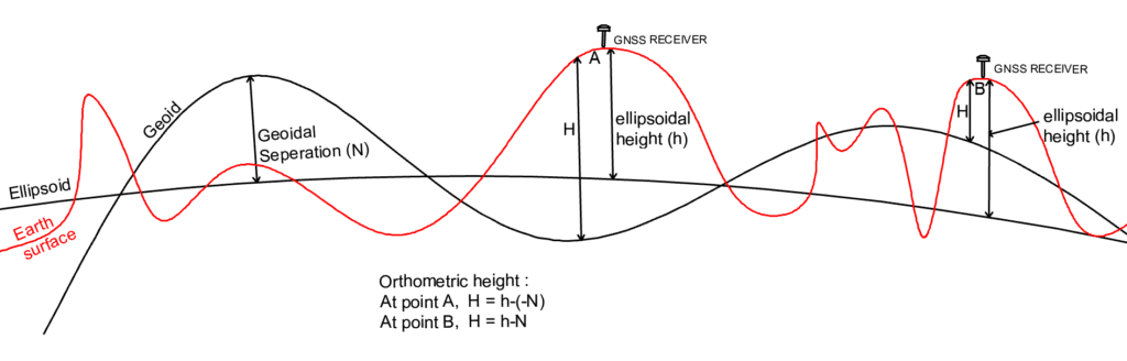
One option for a reference system is the geoid, which is an equipotential surface. Essentially, this means that the force of gravity is constant across the entire surface of the geoid. Interestingly, the geoid closely corresponds to the mean sea level, averaged over a period of 19 years to account for tidal variations.

However, while the geoid is a helpful tool, it’s not quite sufficient as a reference system for geoinformation. Because the density of matter below the Earth’s surface varies, the shape of the geoid itself is not perfectly regular or predictable. This makes it difficult to precisely locate points on the Earth’s surface using the geoid alone.

That’s where the ellipsoid comes in. The ellipsoid is a mathematically-defined surface that fits the Earth’s shape reasonably well, especially in smaller regions. By projecting points from the Earth’s surface onto the ellipsoid, we can get precise XY coordinates for those points. Additionally, we can measure the height of those points above the ellipsoid to get a complete set of coordinates.

Of course, there’s still one problem: the geoid and the ellipsoid don’t match up perfectly. In fact, there can be considerable variation between the two surfaces. To account for this discrepancy, we need to measure the geoidal separation (N) – that is, the distance between the geoid and the ellipsoid at any given point.

geoidal separation (N) - that is, the distance between the geoid and the ellipsoid at any given point.

By combining the geoidal separation with the ellipsoidal height, we can get a full set of coordinates that reflect both the location and the elevation of any point on the Earth’s surface. This powerful combination of reference systems allows us to accurately measure and analyze geoinformation in a way that reflects the true complexity and variability of our planet.

orthometric height

Classification of Surveys:

Surveys play a crucial role in various fields, including engineering, architecture, geology, archaeology, and urban planning. They allow professionals to accurately measure and map out physical spaces, ensuring that projects are designed and executed correctly. Surveys can be classified in several ways, depending on the criteria used. Here are some common classifications of surveys:

Classification Based on Instruments Used:

  1. Chain Survey: This type of survey uses chains or tapes to measure linear distances. The method is based on chain triangulation, where the given area is divided into triangles and the sides of the triangles are measured using a chain. Details are located by taking perpendicular or oblique offsets from the chain line.
  2. Compass Survey: This type of survey uses a compass to measure the bearings of lines with respect to the magnetic north. A series of connected lines are formed, either closed or open traversing, and the bearings of the lines are measured with a compass while the lengths are measured with a chain or tape.
  3. Plane Table Survey: In this type of survey, both the fieldwork and plotting are done simultaneously. A plane table is used to draw a map directly in the field, and details are located by measuring distances and bearing with a chain or tape.
  4. Theodolite Survey: This type of survey uses a theodolite to measure horizontal and vertical angles accurately. It is used for all types of survey work, including triangulation, traversing, and filling in details.
  5. Levelling: This type of survey measures the difference in elevation between points using a level and a graduated pole called a levelling staff.
  6. Tacheometric Surveying: This type of survey uses a tacheometer, which combines the functionality of a theodolite and an EDM (Electronic Distance Meter). It enables the user to measure both horizontal and vertical distances rapidly and accurately.
  7. EDM Survey: This type of survey uses an EDM instrument to measure distances electronically. The instrument emits an electromagnetic signal that is reflected back by a target, and the time delay is used to calculate the distance.
  8. Photogrammetry/Aerial Survey: This type of survey uses aerial photographs to create maps and models of the earth’s surface.
  9. Remote Sensing: This type of survey uses sensors to detect and measure radiation emitted or reflected by the earth’s surface. It can be used for a variety of applications, including land use classification, soil moisture estimation, and crop yield prediction.
  10. Total Station Survey: This type of survey uses a total station, which integrates an EDM, a theodolite, and a data collector. It enables the user to measure angles, distances, and coordinates with high accuracy and efficiency.
  11. GPS Survey: This type of survey uses a Global Positioning System (GPS) receiver to determine the precise location of points on the earth’s surface.

Classification Based on Methods Employed:

  1. Triangulation Surveying: This type of survey establishes a network of triangles to determine the relative positions of points on the earth’s surface.
  2. Traverse Surveying: This type of survey connects a series of lines to form a closed loop or traverse. It is used to determine the relative positions of points and to establish control networks.

Classification Based on the Object of Survey:

  1. Geological Survey: This type of survey is used to study the composition, structure, and processes of the earth’s crust.
  2. Archaeological Survey: This type of survey is used to locate and study historical artifacts and sites.
  3. Mine Survey: This type of survey is used to locate and evaluate mineral resources.
  4. Military Survey: This type of survey is used to establish military bases and installations.

Classification Based on the Nature of the Field Survey:

  1. Marine Surveying: This type of survey is used to study the ocean floor and coastal zones.
  2. Astronomical Surveying: This type of survey is used to determine the precise location and orientation of points on the earth’s surface with respect to celestial bodies.
  3. Land Surveying: This type of survey is used to study the natural and artificial features of the earth’s surface. It can be further classified into topographical, cadastral, city, and engineering surveys.
    1. Cadastral surveying: It Is conducted to determine the boundaries of fields, estates, and houses etc., They are also made to fix the boundaries of municipalities and state and federal jurisdictions.
    2. City surveying: This is carried out to locate the street’s water supply systems, sanitary sewers, and other works.
    3. Topographical Surveying: It Is done to determine the natural features of a country such as lakes, rivers, hills, forests, etc.,
    4. Engineering Surveying: This is done to prepare designs, detailed drawings, and estimates for work such as Roads, Bridges, Reservoirs, etc. In civil engineering, the engineering survey plays an important role. Engineering survey may be further subdivided into.
      1. Reconnaissance Survey: This is conducted to determine the feasibility of work and to prepare a rough cost of the project or scheme.
      2. Preliminary Survey: This survey is conducted to collect more precise data to find the best location or route for the work and to estimate exact quantities and costs.
      3. Location survey: This survey is conducted for setting out the work on the ground.

Overall, surveys play a vital role in understanding the physical world and designing and executing projects that impact our daily lives. Advances in technology continue to improve the accuracy and efficiency of surveys, enabling us to tackle increasingly complex challenges.

Fundamental Principles of Surveying:

The fundamental principles based on the various methods of plane surveying are

  1. To work from whole to the part, and
  2. To locate a new station by at least two measurements (Linear or Angular) from fixed reference points.

1. To work from whole to the part:

The main principle of surveying is working from whole to the part. To satisfy this rule, sufficient number of primary control points are established with higher precision in and around the area to be surveyed. For establishing these points more precise instruments are used. Minor control points are then established by less precise methods and the details can be located using these minor control points by running traverses. The main purpose of this principle is to control the accumulation of errors and to locate the error within the framework of control points. Other wise, if followed a reverse procedure i.e., working from part to whole, the errors would expand to greater magnitude and a stage will come these errors will become uncontrollable.

2. To Locate a New Station by at least Two Measurements (Linear or Angular) from Fixed Reference Points:

According to the second principle, the new stations should always be fixed by at least two measurements (Linear or Angular) from fixed reference points. Linear measurements refer to horizontal distance measured by chain or tape. Angular measurements refer to the magnetic bearing or horizontal angle taken by a prismatic compass or theodolite.

Lets A and B are two reference points. Any other point C can be located by one of the following methods.

 Locate a New Station by at least Two Measurements (Linear or Angular) from Fixed Reference Points

  1. Distance and Angle Measurement: Measure the distance AB and angle, as depicted in Fig. Using this information, plot point C accurately on the plan.
  2. Perpendicular Drop: Drop a perpendicular from point C onto the line AB, as illustrated in Fig. Then, measure either AD and CD or BD and CD to determine the position of C.
  3. Distance Measurements: Measure the distances AC and BC, as shown in Fig. Utilize these measurements to pinpoint the location of point C on the plan.

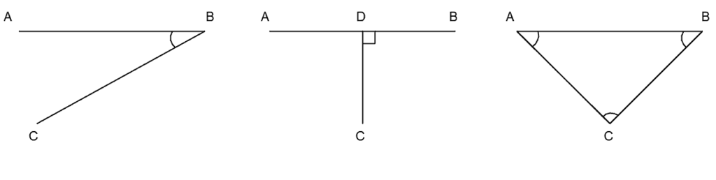
Each method offers its unique advantages, catering to different scenarios and requirements. By understanding these techniques, accurately plotting points on plans becomes more manageable and precise.

Units of Measurements (Linear and Angular) and Conversions:

Linear Measurements:

Linear measurements involve distances along horizontal, vertical, or inclined planes. Traditionally, the Standard of Weights and Measurements Act (India) of 1956 designated meters (\(m\)) and centimeters (\(cm\)) as standard units. In modern practice, the International System of Units (SI) prevails, with measurements typically expressed in meters (\(m\)) and millimeters (\(mm\)). Before the adoption of SI units, linear measurements were often recorded in feet, with subdivisions such as tenths and hundredths of a foot.

\(
\text{SI Units: } 1\, \text{meter} = 100\, \text{centimeters}
\)

Angular Measurements:

Angular measurements are fundamental for determining direction and orientation. They are commonly expressed in degrees (\(^\circ\)) or radians (\(rad\)).

1. The Sexagesimal System:

          In this system, 1 circumference equals \(360^\circ\), with each degree further divided into \(60’\) (minutes) and each minute subdivided into \(60”\) (seconds).

\(
1^\circ = 60′ \quad \text{and} \quad 1′ = 60”
\)

2. The Centesimal System:

          Here, 1 circumference equals \(400\) grads, with each grad further divided into \(100\) centigrade (centi-grad) units.

\(
1\, \text{grad} = 100\, \text{centi-grad}
\)

3. The Hours System:

          Commonly used in navigation and astronomy, this system sets 1 circumference as \(24\) hours, with each hour divided into \(60’\) (minutes) and each minute further subdivided into \(60”\) (seconds).

\(
1\, \text{hour} = 60’\quad \text{and} \quad 1′ = 60”
\)

Instruments Used for Linear Measurements

Linear measurements are fundamental to various surveying techniques and involve determining distances along horizontal, vertical, or inclined planes. To achieve accurate and reliable measurements, surveyors utilize a range of specialized instruments and methods.

Direct Measurement Methods:

  1. Pacing: This method involves pacing the distance between two points and counting the number of paces. The length of the line can then be calculated based on the average length of the pace.
  2. Passometer: A portable device worn on the leg that automatically counts the number of paces.
  3. Odometer: Installed in vehicles to record the number of revolutions of the wheels, which can be converted into distance.
  4. Pedometer: A handheld device similar to a passometer but adjusted to the user’s pace length, directly registering the distance covered.
  5. Speedometer: An instrument fitted in automobiles to measure speed and indirectly calculate distance traveled.
    1.  

Indirect Measurement Methods:

  1. Tacheometer: Measures angles and distances using triangulation and reflection.
  2. Geodimeter: Used to determine precise vertical and horizontal directions.
  3. Tellurometer: Measures long distances using electromagnetic signals.
  4. Photographic Technique: Utilizing photogrammetric methods, this technique involves capturing photographs from known vantage points and determining distances and dimensions through analysis.
  5. Total Station: A surveying instrument that measures angles, distances, and heights using a single point of reference.
    1.  

Instrument used for Angular Measurements

  1. Prismatic or Surveyor’s Compass: A classic tool in surveying, the prismatic or surveyor’s compass is essential for measuring angles and determining directions. It consists of a magnetic needle and a sighting device, allowing surveyors to take precise angular measurements in the field.
  2. Theodolite: A staple instrument in modern surveying, the theodolite is used for measuring horizontal and vertical angles with high accuracy. Equipped with a telescope and graduated circles, the theodolite enables surveyors to precisely determine angular measurements for various survey tasks.
  3. Box Sextant: While less common than the theodolite, the box sextant is still used in certain surveying applications. It utilizes mirrors and a vernier scale to measure angles accurately, particularly in situations where portability is essential.
  4. Abney Level: Primarily used for slope measurement, the Abney level is a versatile instrument that can also measure angles. It features a spirit level and a sighting tube, making it ideal for assessing gradients and inclinations in the field.
  5. Indian Pattern Clinometer: Widely used in geodetic surveys, the Indian pattern clinometer is designed for measuring vertical angles. It provides precise angular measurements for determining elevations and assessing terrain features.
  6. Total Station: A modern surveying instrument, the total station combines electronic distance measurement (EDM) with angle measurement capabilities. Total stations are equipped with electronic theodolites, allowing surveyors to measure angles and distances simultaneously with exceptional accuracy.
Type of Measurement Instruments Used
Linear Measurements
Chain, Tape, Offset Rod, Level, Tacheometer, Geodimeter, Tellurometer, Photographic Technique, Total Station
Angular Measurements
Prismatic or Surveyor’s Compass, Theodolite Box Sextant, Abney Level, Indian Pattern Clinometer, Total Station

Stages of Survey Operation:

Survey operations involve several processes that help create accurate representations of the Earth’s surface. These processes can be broadly classified into three stages: field work, office work, and care and adjustments of instruments. we will explore each stage in detail and discuss their importance in the surveying process.

Stage 1: Field Work

Field work is the first stage of survey operations, where surveyors collect data by taking linear and angular measurements in the field. This stage is crucial as it sets the foundation for the rest of the surveying process. The field work stage can be further divided into three sub-stages:

  1. Reconnaissance: In this sub-stage, the surveyor selects and fixes a number of stations across the area, ensuring necessary intervisibility to establish a system of horizontal control. The surveyor also identifies permanent stations for future reference.
  2. Field Observations: During this sub-stage, the surveyor uses appropriate instruments to make necessary field observations, including measuring horizontal distances, locating details along survey lines, establishing elevations of stations and bench marks, and surveying contours of land areas.
  3. Field Record: After completing the field observations, the surveyor records all the data in a field book. This document serves as the primary source of information for the remaining surveying process. Therefore, it’s essential to maintain accuracy and consistency while recording field observations.

Stage 2: Office Work

Once the field work is complete, the collected data is brought to the office for analysis and processing. The office work stage involves several activities, including:

  1. Data Analysis: The surveyor analyzes the collected data to identify errors, inconsistencies, and missing values. They also perform various calculations to correct the data and ensure it meets the required standards.
  2. Plan Preparation: Using the processed data, the surveyor prepares plans and maps to a standard scale. This stage involves determining areas and volumes for earthwork, locating engineering structures and projects, drawing contours, and selecting the best alignment for roads, railways, and other infrastructure.

Stage 3: Care and Adjustments of Instruments

The final stage of survey operations focuses on caring for and adjusting the instruments used in the field. Precision instruments, such as compasses, levels, theodolites, and EDM devices, require special care to ensure they function accurately. Here are some tips for handling these instruments:

  1. Follow Manufacturer’s Instructions: Always study the manufacturer’s instructions before using the equipment.
  2. Protect Instruments from Sun and Rain: Keep instruments away from direct sunlight and rain to prevent damage. Use a field umbrella to protect them when needed.
  3. Handle with Care: Carry instruments on the shoulder when moving short distances, and use their boxes when transporting them longer distances.
  4. Avoid Smooth Surfaces: Never set instruments on smooth surfaces, as they may slip and fall. If necessary, insert the tripod legs into joints or cracks to stabilize the instrument.
  5. Clean Lenses: Clean lenses regularly to remove dust and moisture. Apply lens cleaning liquid to remove stubborn stains.
  6. Delicate Handling: When operating foot screws and tangent screws, use gentle pressure to avoid damaging the instrument.
  7. Store Instruments Safely: Never leave instruments on roads, footpaths, or unguarded locations. Store them safely in their cases or designated storage areas.

Scales:

Scales are an essential aspect of technical drawing and mapping. A scale refers to the ratio between the actual size of an object and its representation on a drawing or map. There are different types of scales, including:

  1. Full-size scale: This is a scale where the actual size of the object is depicted on the drawing, without any reduction or magnification.
  2. Reduced scale: This is a scale where the actual size of the object is reduced to fit onto the drawing sheet. This is commonly used for plans and maps, where the object being represented is too large to fit on the paper.
  3. Enlarged scale: This is a scale where the actual size of the object is magnified to show greater detail. This is often used for detailed views of machinery or other objects that require close examination.
  4. Representative fraction (RF): This is a scale that represents the ratio of the distance on the map to the corresponding distance on the ground. It is expressed as a fraction, where the numerator is the distance on the map and the denominator is the distance on the ground.
\(\qquad RF = \frac{{\text{Distance on map}}}{{\text{Corresponding actual distance on ground}}} \)
  1. Graphical scale: This is a visual representation of the scale, where a line is sub-divided into equal parts to represent different units of measurement. It is often used in conjunction with a representative fraction.

There are also different types of scales used in technical drawing and mapping, including:

  1. Plain scale: This is a scale that shows only two dimensions, such as length and width. It is commonly used for simple diagrams and sketches.
  2. Diagonal scale: This is a scale that shows three successive units of measurement, such as kilometers, hectometers, and decameters. It is commonly used for maps and plans that require a larger range of measurements.
  3. Vernier scale: This is a scale that has a sliding vernier that allows for precise measurements. It is commonly used for detailed drawings and designs.
  4. Scale of chords: This is a scale that measures the length of curved lines, such as circles or arcs. It is commonly used for architectural and engineering drawings.

The length of a scale should be determined based on the maximum length of the object being represented, and should typically be between 10 and 15 cm. Plans and maps are typically drawn to a smaller scale than actual size, while detailed views of objects may be drawn to a larger scale. Topographic maps also include vertical distances, represented by contour lines, whereas plans do not.

Leave a Reply

Your email address will not be published. Required fields are marked *